

Being interested in nuclear physics and accelerator tech I’m always on the lookout for new high voltage sources. Usually those end up being something along the lines of a big transformer, a CW Multiplier, or a combination thereof. But there are many other methods of generating high voltages which are often overlooked nowadays, and viewed as being outdated.
One of them is the good old Van De Graaff generator, invented in 1929. This is an amazing machine capable of reaching well into the megavolt range that was promptly used to build DC accelerators. The most famous of them being the Westinghouse Atom Smasher, which was used to induce the first detected photofission.
In principle the Van De Graaff generators are very simple devices, but they have undergone many alterations and variations over the years, with their final form being the pelletron. This design is still used today for smallish DC accelerators, most notably built by the high voltage engineering company, founded by mister Van De Graaff himself.
To get my mind away from this semesters finals I decided to build a VDG in its simplest form, the self excited version. The construction is very simple, consisting of mostly 3D printed, lasercut and lathed parts, as well as some stuff from the hardware store and a bit of garden decoration.

The base of my generator is an acrylic plate, which holds the motor from an old garden tool, as well as the bearings for the lower rollers and a holder for the tube though which the transfer belt runs. The lower comb for charge transfer is also mounted here, floating above the belt and bottom roller.


The upper end of the generator is even simpler on construction. It consists of a printed piece sitting on the tube, which has some threaded inserts melted into it, to hold both the bearing blocks for the upper roller, as well as the second comb. The bearing blocks are held in by threaded rods, which hold up a steel profile that holds the top sphere. The comb is directly connected to the bearing blocks through the threaded rods, in my experiments I have found no difference between the bearings being isolated from or connected to the comb.


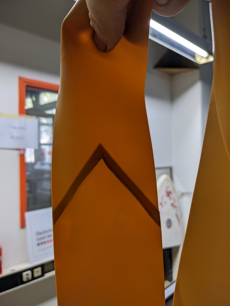
The charge transfer belt is made from latex exersize band, which is sold as “Thera-Band Gold”.
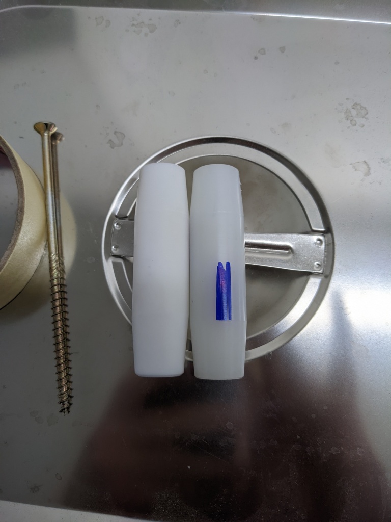
This band is sold in 120 mm wide, but my design called for 80 mm, as well as a closed loop instead of just a strap. With a roller blade the band is quickly cut to size (don’t even try it with a scalpel or similar, it’s absolutely not worth the effort!), and the ends are glued together in a V shape to distrobute the bump along the seam. The rollers are made from PTFE and PA66, both being 80 mm long and 25 mm in diameter, with a 5 degree taper on the ends to keep the belt running true. They’re held on their rods using a m4 grub screw.


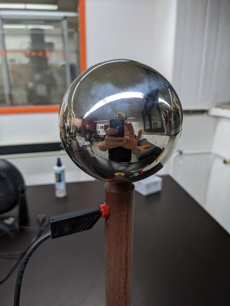
The last part is the top sphere, which serves multiple functions. It stores the transfered charge in order to build up a voltage, it provides a smooth surface to keep the breakdown voltage high, and it acts as a faraday cage, keeping its inside field free. The latter is most important, as it turns the VDG into a true current source, regardless of its terminal voltage.
The main part is a hollow 30 cm diameter stainless sphere sold as garden decoration. This sphere got a hole cut into it, which was “terminated” with a splash guard from a dog food tray in order to provide a smooth bottom lip. The sphere is hold on the generator via a magnet, that attaches to the steel plate above the top roller. This magnet was glued in with hot glue, attached to the plate and then the glue was heated again, allowing the sphere to be centered on the generator so it sat straight with the hole on the bottom.

With the PTFE roller on the bottom and PA66 on the top I get a positive voltage on the terminal, and a current of 15 to 20 µA. To present the flashovers better I built a grounded terminal on a stand, consisting of a phenolic resin rod that hold a 100 mm diameter sphere, as well as a wooden base so it can stand upright. Depending on the humidity I get 20 to 50 cm long sparks, anything above that and the generator strikes into the air instead of to a grounded terminal.


If I were to build a new version of the generator with the goal to use it as a power supply I would do a few things differently. Firstly, I would not build it self excited but instead with external excitation, giving me easy control over the supplied current and polarity. The major difference between the two is that the externally excited one does not rely on the triboelectric effect, but uses metal rollers and a high voltage bias on the bottom comb to spray charge onto the belt.
Other upgrades can improve the transfered current by using multiple combs at different positions, effectively charging the terminal both on the belts way up and down.
Another important upgrade would be some effective field shaping, in order to lower the electric field strength on the terminal and reduce flashovers in the air. Since the top terminal is spherical its electric field is proportional to 1/r², resulting in a high field on the surface.
Using grading rings from the terminal to ground and biasing them through a linear voltage divider can shape the field to be more linear and have the same value throughout.
These grading rings can be seen on commercial Van De Graaff accelerators, and they greatly help to achieve higher, more stable voltages.
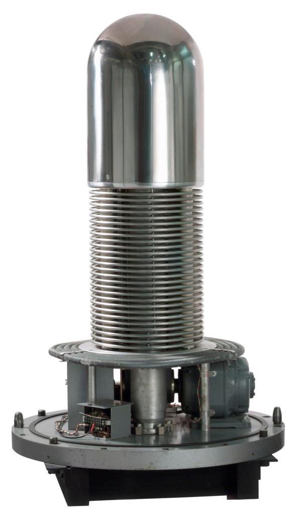
Taken from: https://collection.sciencemuseumgroup.org.uk/objects/co5505/van-de-graaff-accelerator-1920-1979-van-der-graaff-accelerator
This linearisation can easily be demonstrated with a simple python script that simply plots both the spherical field as well as an idealized linear field at any given voltage, sphere size and distance to ground. Of course it has some big assumptions, but it displays the general idea pretty well. In ambient air 1 MV/m is a well accepted value for a discharge to happen.

